Bio: Nitheesh is the founder of MentorCrux, an India-based mentorship platform for core engineers. His mission is to create a space where expert knowledge is accessible to all, providing the tools and insights necessary for professional growth in the core engineering sector.
A core engineering recruiter spends roughly 10 seconds on your portfolio in the job application. If they see a “rainbow plot” without a mesh study or a clear justification for your boundary conditions, they are already moving to the next candidate.
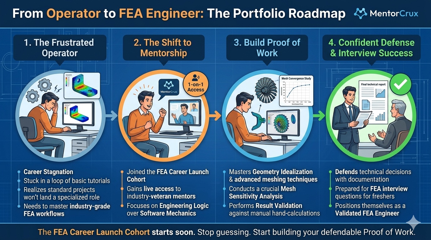
At MentorCrux, our analysis of hiring requirements at top tier firms shows a clear trend. The industry has an oversupply of “Software Operators” but a critical shortage of “FEA Engineers.” An operator knows which buttons to click in Ansys to get a colorful result. An engineer understands the physics behind the result and knows exactly how to validate it.
If your FEA portfolio for engineers consists of simple parts with generic fixed supports, it doesn’t demonstrate engineering skill; it only shows you can follow a software tutorial. To land a core role in 2026, your portfolio must shift from showing results to explaining engineering logic.
1. The Problem with Unvalidated Simulations
Freshers often present contour plots as final proof of their work. However, in a professional design office, a stress plot without context is considered a “Colorful Lie.” Red usually indicates high stress, but without proper setup, it often simply signals a “Singularity” or an incorrect boundary condition.
Currently, the Indian Engineering Research & Development (ER&D) market is projected to reach $120 Billion by 2030 according to NASSCOM. This growth is driven by high-end simulation, yet firms struggle to find talent familiar with industry-grade FEA workflows.
When our mentors review a portfolio, they look for a Mesh Convergence Study. If you cannot prove that your results stay consistent regardless of your element size, the simulation is technically unreliable.
2. The 3 Pillars of an Industry-Grade FEA Portfolio
To build a professional mechanical design engineer portfolio, you must demonstrate a workflow built on these three technical pillars.
Pillar 1: Geometry Idealization (The Art of Simplification)
Professional FEA involves analyzing an “Efficient” model rather than a “Perfect” CAD model. In a real-world project, a CAD file might contain thousands of tiny details—logos, tiny fillets, bolt threads, and aesthetic chamfers.
Why this matters: If you try to mesh these details, your element count will skyrocket, leading to massive solve times or software crashes. What to show in your portfolio:
- Defeaturing: Show a “Before” and “After” of your CAD model. Explain why you removed non-structural features that don’t affect the load path.
- Abstraction: Did you use a 1D Beam element for a long, slender rod? Did you use 2D Shell elements for thin sheet metal? Explaining these choices proves you understand computational efficiency.
Pillar 2: Mesh Convergence (The Trust Factor)
A single simulation is just a starting point. A common mistake freshers make is assuming the software’s default mesh is “correct.”
What is Mesh Convergence? It is the process of refining your mesh (making elements smaller) until the stress value stops changing significantly. The Workflow:
- Run the simulation with a coarse mesh.
- Refine the mesh in areas of high stress and re-run.
- Repeat until the difference between two iterations is less than 2-5%. What to show: A graph plotting “Number of Elements” vs. “Max Von-Mises Stress.” If your portfolio contains this graph, you have already outperformed 90% of other applicants.
Pillar 3: Result Validation (Manual Checks)
This is the ultimate test of an engineer. You must prove the software results are accurate. This is why core engineering students need Matlab and Ansys early; you must be able to use manual hand-calculations or analytical methods (like Beam Theory or Peterson’s Stress Concentration factors) to verify your simulation within a reasonable margin.
3. Deep Dive: Load Paths and Boundary Conditions
One of the hardest things for a recruiter to verify is if you understand how forces actually move through a structure.
Understanding Load Paths
Before you assign a “Force” in your software, you must be able to visualize the “Load Path.” This is the journey a force takes from the point of application to the point of support. If you place a boundary condition (support) in a way that “locks” the structure unnaturally, your stress results will be artificially high or low.
The Problem with “Fixed Supports”
In college, every support is a “Fixed Support.” In reality, nothing is perfectly rigid. If you are analyzing a car’s suspension arm, is the mounting point truly fixed? Or does it have some rotational freedom? Discussing these nuances in your portfolio shows that you are thinking about the physics of the assembly, not just the software buttons.
4. What Recruiters Test: The “What-if” Scenarios
In interviews for roles in aircraft structures or aircraft design, recruiters use “What-if” scenarios to see if you have a “feel” for the numbers. According to the Deloitte Aerospace & Defense report, the industry is moving toward “Digital Twins,” where accuracy is the only priority.
Common Technical Assessment Questions:
- Linear vs. Non-linear: “If you double the load on this bracket, will the stress always double?” (If you say yes, you might be ignoring material yielding or geometric non-linearity).
- Singularities: “Why is there a red spot at this sharp internal corner? Is the part really going to fail there?” (An engineer knows this is often a mathematical artifact called a ‘Stress Singularity’ that needs to be addressed with a radius or ignored).
- Mass Participation: In a dynamic or modal analysis, how much of your structure’s mass is actually moving?
5. The Role of Documentation in an FEA Career
In a professional design office, the “Simulation Report” is the final product. Your portfolio should look like a collection of these reports.
A professional report structure includes:
- Objective: What problem are we solving? (Weight reduction, factor of safety check, etc.)
- Assumptions: What material properties were used? Is it an isotropic or anisotropic material?
- Boundary Conditions: Clear images showing where loads and supports were applied.
- Verification: The hand-calculations mentioned earlier.
- Conclusion & Recommendations: Don’t just say “The stress is 200 MPa.” Say “The stress is 200 MPa, which gives us a Factor of Safety of 1.5. I recommend increasing the thickness of the ribs by 2mm to reach a FOS of 2.0.”
The Founder’s Perspective: Solving the “Unemployability” Gap
Having a degree and knowing how to use Ansys are two different things. Statistics from the National Employability Report suggest that only 3.84% of engineers are employable in software-related core engineering roles.
This is the gap we are solving at MentorCrux. We saw brilliant students who could solve complex differential equations but couldn’t explain why a mesh failed to converge. This “Industry-Unready” status is what keeps freshers stuck in low-paying site jobs instead of high-end design offices.
We brought in industry-veteran FEA Mentors—professionals who have spent decades performing structural audits for global OEMs—to design our curriculum. We don’t want you to finish a cohort with just a certificate; we want you to finish with a defendable, industry-grade project. This is the core strategy detailed in our career roadmap for aerospace engineers.
7. Future-Proofing Your Career: FEA in 2026 and Beyond
As we move deeper into 2026, the tools are becoming more automated. AI-driven “Generative Design” can now suggest shapes for us. However, this makes the role of the FEA engineer more important, not less.
An AI can suggest a shape, but it cannot “sign off” on its safety. It cannot understand the legal implications of a structural failure. The future of core engineering belongs to those who can audit the results of the software. Your value lies in your ability to say: “I trust these results because I validated them.”
The MentorCrux Edge: Join the FEA Career Launch Cohort
Industry firms do not pay for the simulation; they pay for the Interpretation of the data.
Starting in a few days, our 3-month FEA Career Launch Cohort will move you beyond recorded videos and into live, mentor-guided sessions. This is specifically designed for engineers who are technically capable but lack the “Industry-Grade” portfolio needed to break into top design firms.
Key Mastery Areas:
- Physics-based Boundary Conditions: Understanding real-world constraints beyond “fixed” supports.
- Mesh Sensitivity Analysis: Learning to defend your element selection in an interview.
- Validation Techniques: Using hand-calculations to verify FEA output and build recruiter trust.
By the end of this cohort, you won’t just have a project; you will have a project you can confidently defend in front of a senior design lead.
[Apply for the FEA Career Launch Cohort Today]
Your degree got you the interview. Your portfolio will get you the job.
Are you struggling with a specific simulation or boundary condition right now? Mention your problem in the comments, and I’ll ask one of our FEA Mentors to give you a “Physics-Check” on your approach.
Leave a Reply